Digital clock using 4026 ic:
Proteus Circuit diagram:
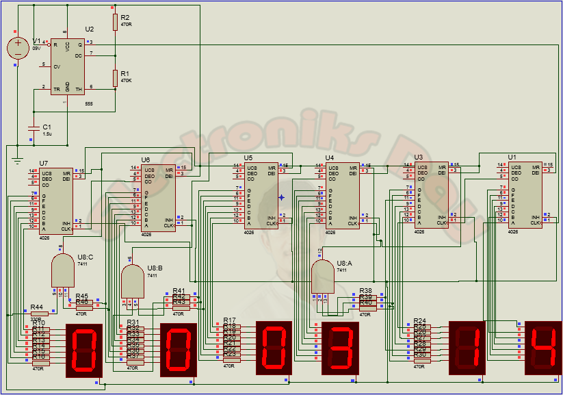
Digital Clock Using 4026 IC
Components required:
· 555 Timer
· IC 4026
· IC 7411 (Three input AND Gate)
· 7-Segment common cathode display
· 1.5uF Capacitor.
· 470 ohm and 470 kilo ohm resistors.
· 9V Battery
· IC 4026
· IC 7411 (Three input AND Gate)
· 7-Segment common cathode display
· 1.5uF Capacitor.
· 470 ohm and 470 kilo ohm resistors.
· 9V Battery
About components:
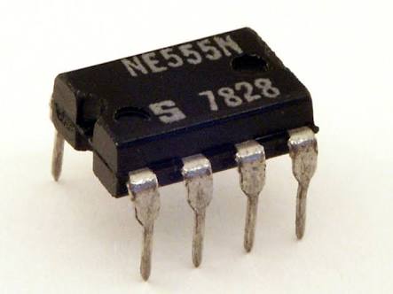
555 Timer:
The 555 is basically a monostable Multivibrator. The important characteristics of a Monostable Multivibrator is as long as the pin 2 receives a positive trigger the output at pin 3 will be of low state. And when negative trigger was fed into the pin 2, the output at the pin 3 will go high for a specific period of time. This time was decided by the Resistor and Capacitor connected with it. You can see my post "How to properly use 555 timer" for help, link is given at the end of page.
IC 4026:
The 4026 IC is a 16-pin CMOS seven-segment counter from the 4000 series. It counts clock pulses and returns the output in a form which can be displayed on a seven-segment display. This avoids using a binary-coded decimal to seven-segment decoder, but it can only be used to display the (decimal) digits 0-9.
IC 7411:
The IC 7411 is basically AND Gate having three inputs and one output. This IC contains three AND Gates.
Working:
The working of the circuit starts with the 555 timer where it was wired as a monostable Multivibrator. The 555 timer generate clock pulse after a second and output of 555 is connected to pin 1 of IC 4026 which is a seven segment display decade counter which is used to drive a 7 segment display with input clock pulse. Here the clock pulse was obtained from the monostable multivibrator and fed into the pin 1 of first ic 4026. Pin 2 was usually grounded since giving high signal to this pin will inhibit the input clock signal to pin 1 and pin 3(Enable Clock) is always taken High.
Initially when the circuit is switched ON the 7 segments will indicate "00:00:00" count and as soon as the negative trigger was given to 555 high pulse will be obtained from pin 3. The high pulse was fed to first IC and therefore it increments its count with each clock, displaying 1 to 9 in its seven segment. As soon as 10 counts was incremented by IC a high to low signal was obtained from its pin 5 which indicates the completion of ten increments.
The pin 5 was connected to the clock pin of the next 4026 IC. Therefore whenever 10 counts was completed by the 7 segment, the high to low signal at the pin 5 will feed a single clock pulse input to the second IC and therefore the corresponding 7 segment will be incremented one value. For a digital clock we must reset second IC when it reach to number 6 because we want seconds count upto "59" therefore we used IC 7411 (Three input AND Gate). In the same manner fourth IC will count from 0 to 6 and then value in the fifth IC will be incremented by one. This is all about for seconds and minute of clock. Now for hours we must reset fifth and sixth IC when number reached to “23” so we put one more three input AND gate.
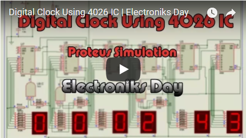
Video Tutorial:
Here is complete video tutorial with design and working of 24H digital clock using 4026 IC, Download link for this simulation is in the description of video. This is my new youtube channel please subscribe, comment and like video if it helps you. Thanks
Author: Engr. Hassam Bin Hassan
You may also like these
How to properly use 555 timer
|
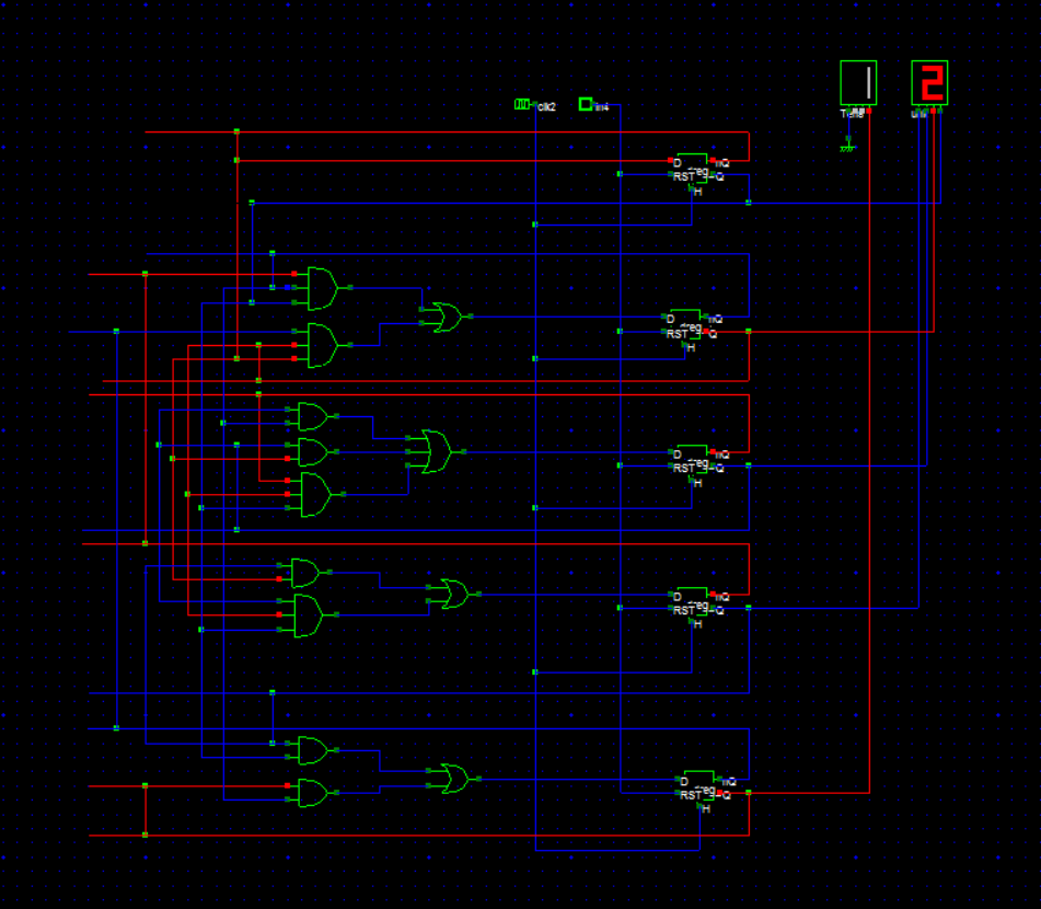
12 Hours Digital Clock Using Logic Gates and Flip Flops
|
