Proteus Circuit Diagram PIC16f877a
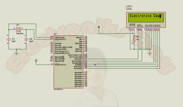
Interfacing 16x2 LCD with PIC16f877a
16x2 LCD is basic output module used in microcontroller based projects. It has 16 columns and 2 rows to display characters. It can be easily interfaced with PIC microcontroller. In this tutorial we will see how to interface 16x2 LCD with PIC 16f877a using “MikroC PRO for PIC v6.6.1” compiler.
Software Required:
1- MikroC PRO for PIC (version 6.6.1 is good enough for this tutorial, NOTE: latest version will give errors. )
2- Proteus (v7.8 or 8)
2- Proteus (v7.8 or 8)
Hardware Required:
1- PIC16f877a
2- 16x2 LCD
3- 20MHz oscillator
4- 22pf capacitors (2)
5- 10K variable resistor
6- 9 volts battery
7- 7805 voltage regulator
2- 16x2 LCD
3- 20MHz oscillator
4- 22pf capacitors (2)
5- 10K variable resistor
6- 9 volts battery
7- 7805 voltage regulator
Procedure:
Now make sure you have all this stuff, first of all create new project in MikroC, choose your Microcontroller i.e PIC16f877a and set frequency 20MHz (this is basically the frequency of oscillator, in our case we have used 20MHz). If MikroC asks to import libraries then click OK to import all libraries. Create a new C file for you project and add the C code (comment your email address for source code) and save your project. Now it’s time to build .HEX file (we need this file for Simulation and Hardware) you can find BUILD on the top layer of MikroC simply click on it or just press Ctrl+F9. .HEX file is now saved in your project folder.
For Proteus simulation open the .DSN simulation file (comment your email address for simulation file). You will see PIC16f877a in simulation double click on it and add the .HEX file you generated in MikroC. Now run the Simulation and wow LCD is interfaced with PIC microcontroller. If you have any question leave a comment.
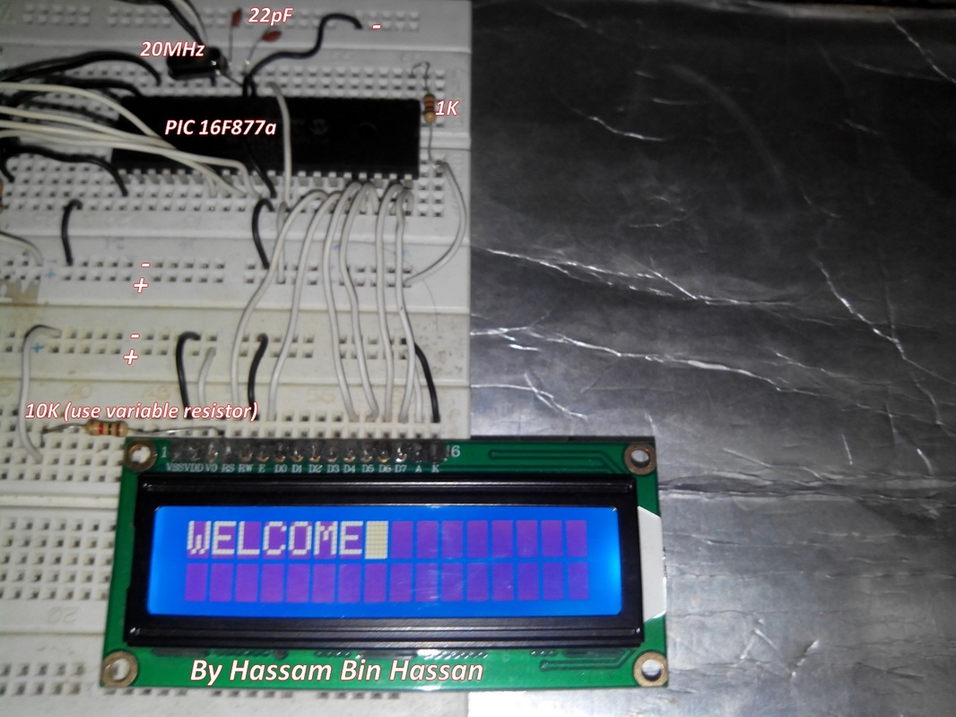
Also want to implement this on hardware?? Yes, so keep reading. It’s not as hard as you are thinking just connect all wires as in simulation. Make sure your wires are not loose otherwise you will face lot of problems. Connect pin 15 of LCD to +5 Volts and Pin 16 to ground. Now connect PIN 3 of LCD with 10K variable resistor to ground. Again make sure your LCD PIN 3 is properly connected otherwise even if everything is working properly you can’t see anything on LCD. Now apply 5v to PIC16f877a and LCD. If u are using 9v battery then use 7805 voltage regulator to regulate voltage to +5v. If u are not sure how to use 7805 regulator see my article “7805 voltage regulator”. Set the contrast of LCD by varying 10k resistor.
If your LCD display is something like this
For Proteus simulation open the .DSN simulation file (comment your email address for simulation file). You will see PIC16f877a in simulation double click on it and add the .HEX file you generated in MikroC. Now run the Simulation and wow LCD is interfaced with PIC microcontroller. If you have any question leave a comment.
Also want to implement this on hardware?? Yes, so keep reading. It’s not as hard as you are thinking just connect all wires as in simulation. Make sure your wires are not loose otherwise you will face lot of problems. Connect pin 15 of LCD to +5 Volts and Pin 16 to ground. Now connect PIN 3 of LCD with 10K variable resistor to ground. Again make sure your LCD PIN 3 is properly connected otherwise even if everything is working properly you can’t see anything on LCD. Now apply 5v to PIC16f877a and LCD. If u are using 9v battery then use 7805 voltage regulator to regulate voltage to +5v. If u are not sure how to use 7805 regulator see my article “7805 voltage regulator”. Set the contrast of LCD by varying 10k resistor.
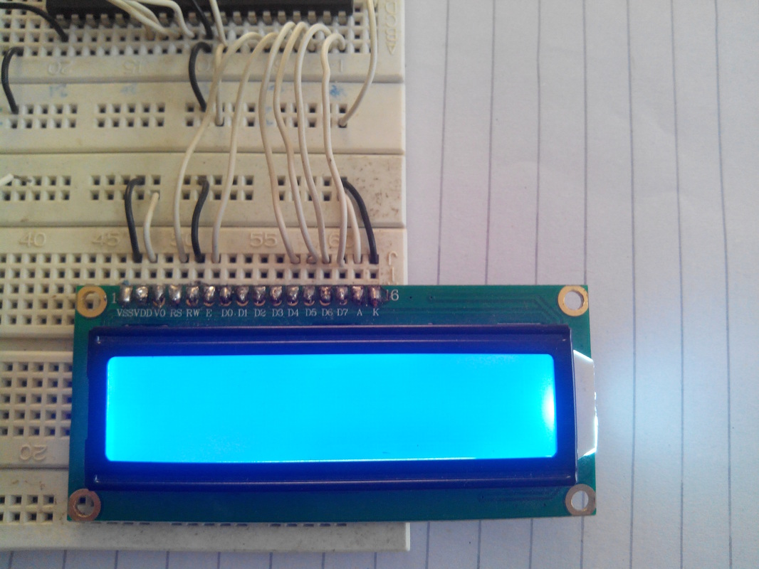
If your LCD display is something like this
then your LCD is not damaged and is working perfectly check if your PIN 3 (contrast PIN) is properly connected to 10K variable resistor. Adjust the contrast by changing variable resistor value. If problem is not solved check microcontroller PIN 1, connect PIN 1 of PIC with 1k resistor to +5v, also check oscillator again.
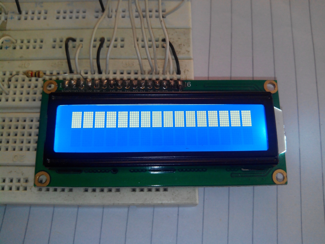
If your LCD display looks like this, as below image then either you forget to connect 10k variable resistor with PIN 3 of LCD or your LCD is damaged.
Hardware Snapshot:
Video Tutorial:
Here is complete video tutorial with design, source code and working of LCD with PIC16f877a, Download link for the simulation and source code is in the description of video. This is my new youtube channel please smile, subscribe, comment and like video if it helps you. Thanks