Distance Measurement Device using IR sensor with PIC microcontroller:
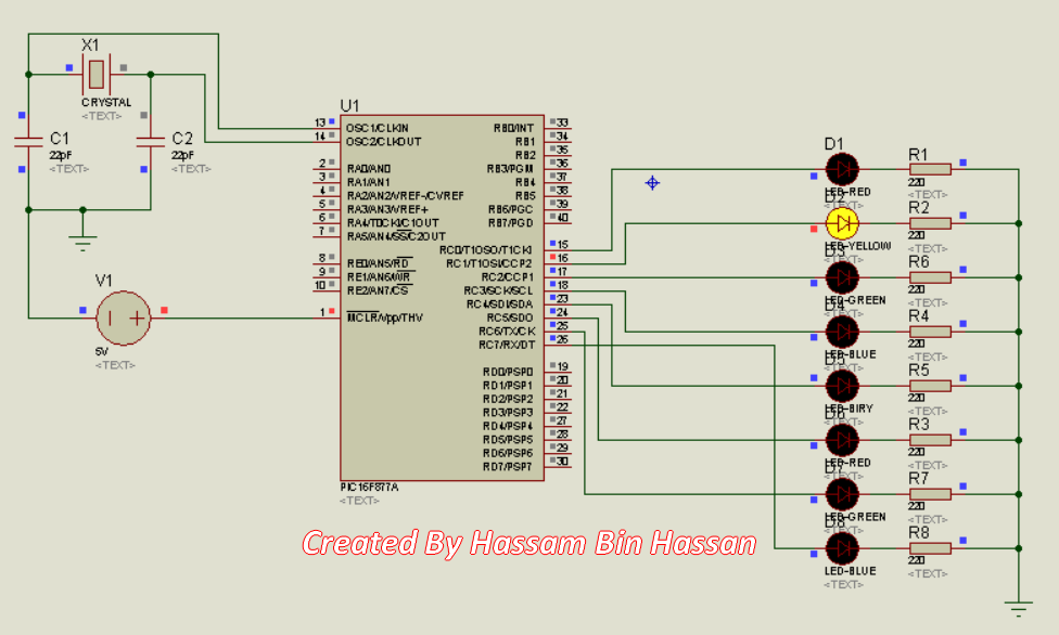
Proteus Simulation Diagram:
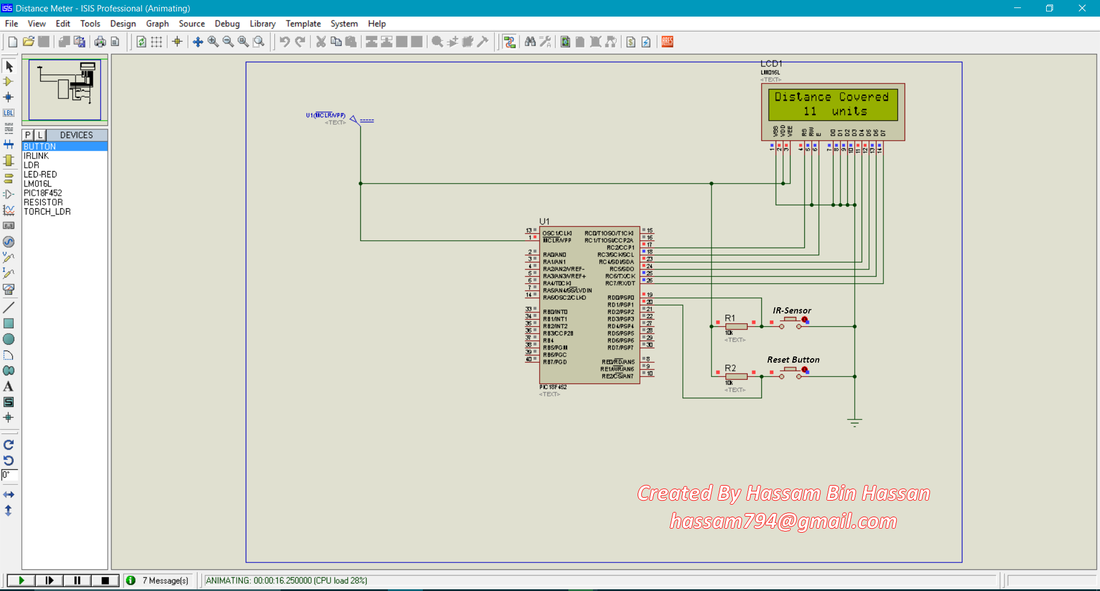
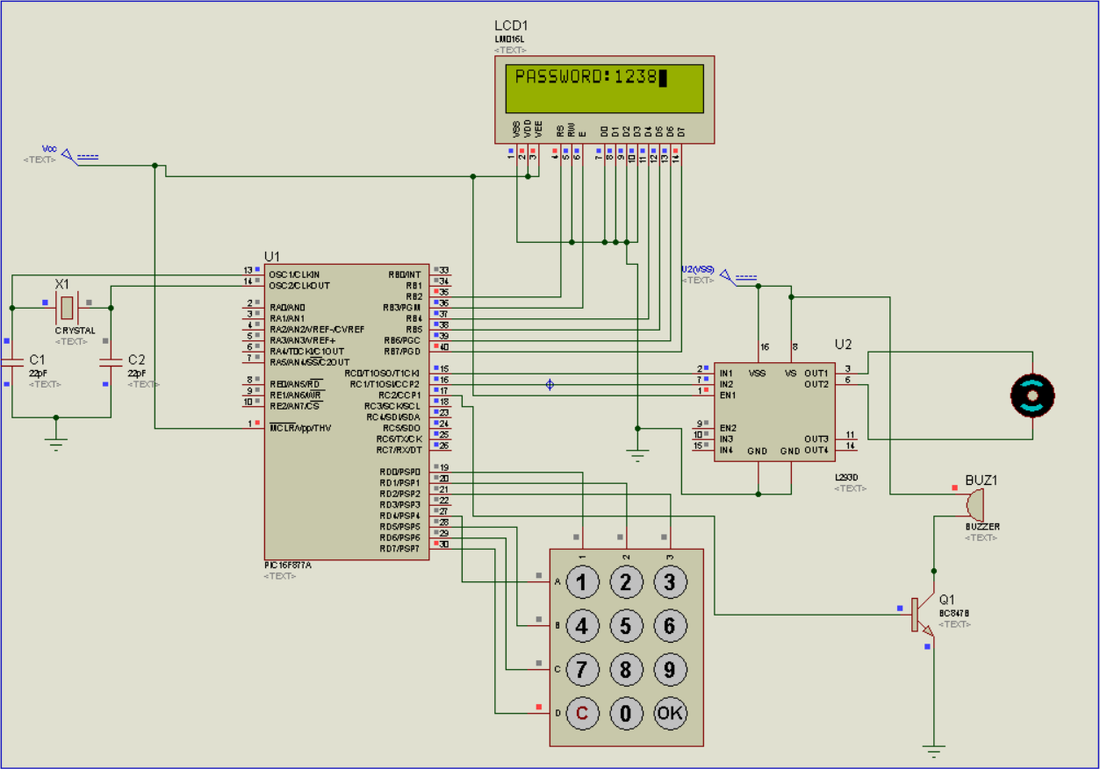
Proteus Simulation
Software Required:
1- MikroC PRO for PIC (version 6.6.2 is good enough for this tutorial, NOTE: latest version will give errors)
2- Proteus ISIS ( v7.8 or Proteus 8)
2- Proteus ISIS ( v7.8 or Proteus 8)
Hardware Required:
1- PIC16f877a
2- 16x2 LCD
3- 4MHz oscillator
4- 22pf capacitors (2)
5- 10K variable resistor
6- 9 volts battery
7- 7805 voltage regulator
8- IR Sensor
9- Push Button
2- 16x2 LCD
3- 4MHz oscillator
4- 22pf capacitors (2)
5- 10K variable resistor
6- 9 volts battery
7- 7805 voltage regulator
8- IR Sensor
9- Push Button
Working:
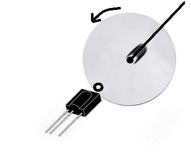
It is modern distance measurement device using IR Sensor. IR Senor has a Transmitter and Receiver. IR sensor give output as signal HIGH or LOW. If we place any object in front of IR sensor it give HIGH output signal otherwise signal remains LOW. So are you wondering how we will use IR Sensor as distance measurement device?? Pretty Cool. Let me explain. We are using a round disc wheel with a hole on its corner and IR sensor is fixed in front of hole as shown in figure below. Now place the disc wheel on ground and start rotating wheel when disc hole comes in front of IR Sensor after a complete rotation then IR sensor gives a LOW signal and we increment distance by one unit. After a one complete round of disc wheel our distance will be equal to the circumference of disc used.
Circumference = 2 x (pi) x Radius
Total distance = round count x circumference
Now multiply the round count by circumference and display on LCD. So we can easily measure distance using this device.
Note: To get more accuracy increase the number of holes on disc and use the formula below
Total distance= count x (circumference/number of holes)
This will give more accurate results.
Procedure:
Now make sure you have all this stuff, first of all create new project in MikroC, choose your Microcontroller i.e PIC18f452 and set frequency 4MHz (this is basically the frequency of oscillator, in our case we have used 4MHz). If MikroC asks to import libraries then click OK to import all libraries. Create a new C file for you project and add the C code (comment your email address for source code) and save your project. Now it’s time to build .HEX file (we need this file for Simulation and Hardware) you can find BUILD on the top layer of MikroC simply click on it or just press Ctrl+F9. .HEX file is now saved in your project folder.
For Proteus Simulink open the .DSN simulation file (comment your email address for simulation file). You will see PIC18f452 in simulation double click on it and add the .HEX file (you generated in MikroC). Now run the Simulation and wow our distance measurement device is ready. If you have any question leave a comment.
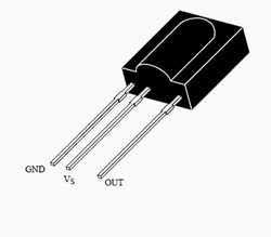
Also want to implement this on hardware?? If Yes, so keep reading. It’s not as hard as you are thinking just connect all wires as in simulation. Make sure your wires are not loose otherwise you will face lot of problems. First of all interface LCD to make sure your circuit is working. If you have problem interfacing LCD please read my article Interfacing 16x2 LCD with PIC16f877a. I have covered all basic problem regarding LCD interfacing. So when u have working LCD then come to next point IR sensor interfacing. In Proteus we don’t have useful IR sensor, there is one IRLINK module in Proteus but it is useless in our case so I have used push button (attached with R1) on Proteus simulation. We can use IR Sensor on Hardware rather than using push button. IR Sensor has three pins VCC, ground and output as shown in figure below. Attach the output pin of IR sensor at 19th PIN of microcontroller (with out using resistor) and also interfacing Rest Button (attached with R2) that’s done our project is ready. If you have any question leave a comment.
For Proteus Simulink open the .DSN simulation file (comment your email address for simulation file). You will see PIC18f452 in simulation double click on it and add the .HEX file (you generated in MikroC). Now run the Simulation and wow our distance measurement device is ready. If you have any question leave a comment.
Also want to implement this on hardware?? If Yes, so keep reading. It’s not as hard as you are thinking just connect all wires as in simulation. Make sure your wires are not loose otherwise you will face lot of problems. First of all interface LCD to make sure your circuit is working. If you have problem interfacing LCD please read my article Interfacing 16x2 LCD with PIC16f877a. I have covered all basic problem regarding LCD interfacing. So when u have working LCD then come to next point IR sensor interfacing. In Proteus we don’t have useful IR sensor, there is one IRLINK module in Proteus but it is useless in our case so I have used push button (attached with R1) on Proteus simulation. We can use IR Sensor on Hardware rather than using push button. IR Sensor has three pins VCC, ground and output as shown in figure below. Attach the output pin of IR sensor at 19th PIN of microcontroller (with out using resistor) and also interfacing Rest Button (attached with R2) that’s done our project is ready. If you have any question leave a comment.
IR Sensor
Author: Engr. Hassam Bin Hassan
You may also like
Disco Pattern LEDs using Microcontroller
|
Password Based Security Door Lock System
|
