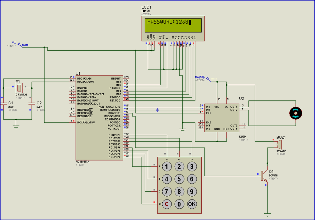
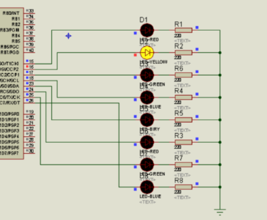
Proteus Simulation Circuit Diagram:
Software Required:
1- MikroC PRO for PIC (version 6.6.2 is good enough for this tutorial , NOTE: latest version will give errors)
2- Proteus (v7.7 or 8)
2- Proteus (v7.7 or 8)
Hardware Required:
1- PIC16f877a
2- 16x2 LCD
3- 20MHz oscillator
4- 22pf capacitors (2)
5- 10K variable resistor
6- 9 volts battery
7- 7805 voltage regulator
8- 4x3 Keypad
9- L293D IC
10- 10k resistor (for keypad)
11- Buzzer and BC847 transistor
2- 16x2 LCD
3- 20MHz oscillator
4- 22pf capacitors (2)
5- 10K variable resistor
6- 9 volts battery
7- 7805 voltage regulator
8- 4x3 Keypad
9- L293D IC
10- 10k resistor (for keypad)
11- Buzzer and BC847 transistor
Working:
First of all when you connect power supply then microcontroller, LCD and L293D ic is in working state now. Microcontroller will initialize LCD on port B and keypad on Port D and set port C to output. We have used pin 0 and 1 of port c to control L293D ic. Now every thing is ready and when keypad button is pressed microcontroller will reads value and save this value in array and convert key value to its ascii to display it on LCD. Its four digit password after entering four digits press OK button then its will compares the saved password and user entered password after that there are two possibilities.
1-Password Correct:
If both strings matches then it will send signal to L293D ic and rotates motor in clock wise direction. And then its asks to close the door by pressing digit one. Same logic is used to rotate motor anticlockwise.
2-Password Incorrect:
If password is incorrect it will halt user and beeps buzzer and decrements ''No of attempts'' by one. If no of attempt is less then 0 it will block the user to enter password.
Procedure:
Now make sure you have all hardware elements, first of all create new project in MikroC, choose your Microcontroller i.e PIC16f877a and set frequency 20MHz (this is basically the frequency of oscillator, in our case we have used 20MHz). If MikroC asks to import libraries then click OK to import all libraries. Create a new C file for you project and add the C code (comment your email address for source code) and save your project. Now it’s time to build .HEX file (we need this file for Simulation and Hardware) you can find BUILD on the top layer of MikroC simply click on it or just press Ctrl+F9. .HEX file is now saved in your project folder.
For Proteus simulation open the .DSN simulation file (comment your email address for simulation file). You will see PIC16f877a in simulation double click on it and add the .HEX file you generated in MikroC. Now run the Simulation and wow its working. If you have any question leave a comment.
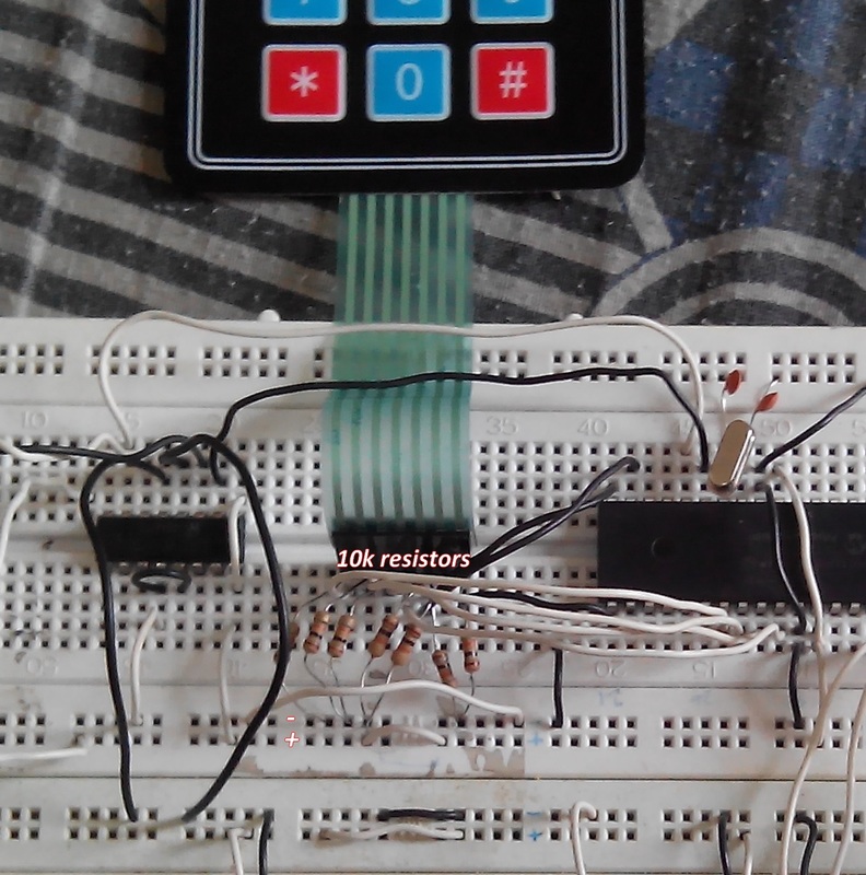
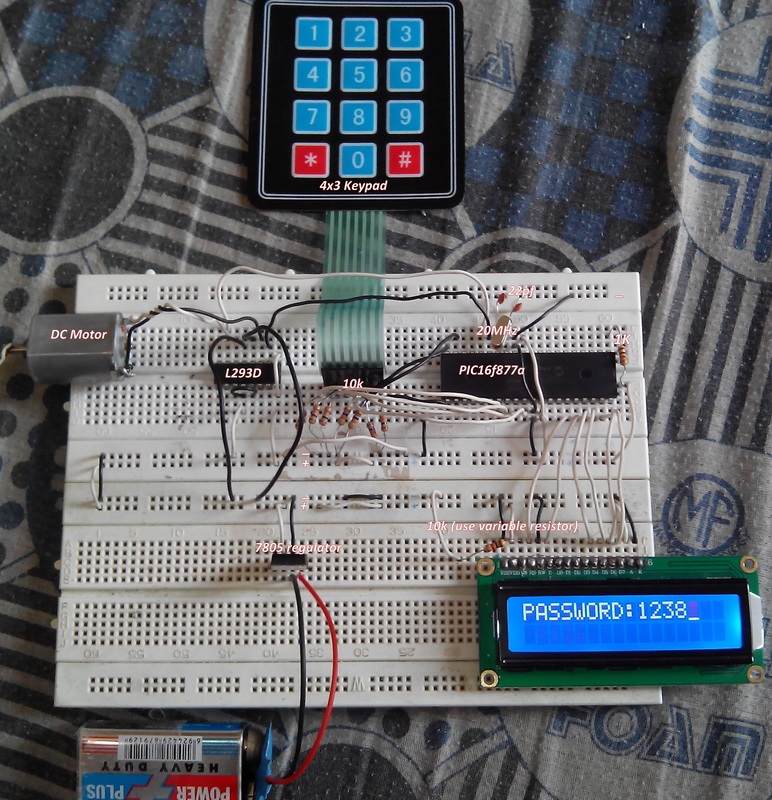
Also want to implement this on hardware?? Yes, so keep reading. It’s not as hard as you are thinking just connect all wires as in simulation. Make sure your wires are not loose otherwise you will face lot of problems. First interface LCD, don't jump on motor driver IC L293D and Keypad. I suggest you to read Interfacing 16x2 LCD with PIC16f877a if you are facing problems. Now come to 4x3 keypad, connect wires as shown in figure above, if your keypad is generating random numbers on LCD or misbehaves then make sure you have connected 10k resistance with keypad to ground on each keypad pin. See the hardware snapshot below. I am sure this will fix your problem
For Proteus simulation open the .DSN simulation file (comment your email address for simulation file). You will see PIC16f877a in simulation double click on it and add the .HEX file you generated in MikroC. Now run the Simulation and wow its working. If you have any question leave a comment.
Also want to implement this on hardware?? Yes, so keep reading. It’s not as hard as you are thinking just connect all wires as in simulation. Make sure your wires are not loose otherwise you will face lot of problems. First interface LCD, don't jump on motor driver IC L293D and Keypad. I suggest you to read Interfacing 16x2 LCD with PIC16f877a if you are facing problems. Now come to 4x3 keypad, connect wires as shown in figure above, if your keypad is generating random numbers on LCD or misbehaves then make sure you have connected 10k resistance with keypad to ground on each keypad pin. See the hardware snapshot below. I am sure this will fix your problem
If your Keypad and LCD are working now its time for L293D ic. Its just simple connect all wires as in simulation file. If your program misbehaves after connecting L293D then make sure L293D has separate power supply at PIN 8 to rotate motor. If u have any question contact me.
Hardware Snapshot:
Author: Engr. Hassam Bin Hassan
Some guyz are asking for LCD interfacing Problems, Please read this complete tutorial.
https://hassam794.weebly.com/interfacing-16x2-lcd-with-pic16f877a.html
And i also uploaded complete video tutorial on my new youtube channel for lcd interfacing. Must subscribe for more projects.
https://youtu.be/tn0rzz67z0A
you may also like
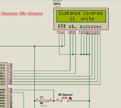
Distance Measurement Device using IR sensor with PIC16f877a
|
LED blinking Pattern
|
