• Home
  • Microcontroller Projects
    • Distance Measurement Device using IR Sensor with PIC microcontroller
    • Password Based Security Door Lock using pic16f877a
    • Interfacing 16x2 LCD with PIC16f877a
    • Blinking LEDs pattern using PIC16f877a
  • Digital Logic Design Project
    • Digital Clock Using 4026 IC
  • Electronics Projects
  • Contact
  Electrical Electronics

How to properly use 555 timer

6/17/2016

2 Comments

 
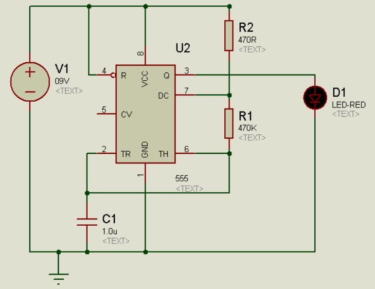
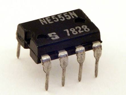
The 555 timer is the most popular integrated chip. It is used as oscillator in electronics circuits, the 555 timer is capable of being used in astable and mono stable circuits. Its output always alternates between VCC and zero volts. 555 timer is usually used in counter IC's and where we need clock pulse, so it is important to know how to properly wire 555 timer circuit and how to set required duty cycle of output clock. 
You can set duty cycle of output clock by changing the values of R1, R2 and C1 as follows
1-    Increasing R1 will increase High Time and increase Low time.
2-    Increasing R2 will increase High Time but will not change low time
3-    Changing C1 will change cycle time and reduce the frequency of output generated clock.
​
Note: If your timer is not working check pin number 4 (Reset Pin), as you can see in diagram pin 4 is active low so make sure it is connected to positive terminal.
Picture
Picture
2 Comments
Kewal
10/22/2018 08:15:11 pm

Nice

Reply
Abel Xavier
10/29/2018 06:19:07 pm

I need to build in proteus a chronometer with only one buton. start, stop and reset when i press to long. the chronometer count until 99h.
regards in advance

Reply


Leave a Reply.

    Author

    Hassam Bin Hassan

    BS in Electrical (Electronics) Engineering

    Picture
    .

    Contact

    [email protected]
Powered by Create your own unique website with customizable templates.
  • Home
  • Microcontroller Projects
    • Distance Measurement Device using IR Sensor with PIC microcontroller
    • Password Based Security Door Lock using pic16f877a
    • Interfacing 16x2 LCD with PIC16f877a
    • Blinking LEDs pattern using PIC16f877a
  • Digital Logic Design Project
    • Digital Clock Using 4026 IC
  • Electronics Projects
  • Contact